★ Pass on Your First TRY ★ 100% Money Back Guarantee ★ Realistic Practice Exam Questions
Free Instant Download NEW JN0-664 Exam Dumps (PDF & VCE):
Available on:
https://www.certleader.com/JN0-664-dumps.html
Passleader offers free demo for JN0-664 exam. "Service Provider - Professional (JNCIP-SP)", also known as JN0-664 exam, is a Juniper Certification. This set of posts, Passing the Juniper JN0-664 exam, will help you answer those questions. The JN0-664 Questions & Answers covers all the knowledge points of the real exam. 100% real Juniper JN0-664 exams and revised by experts!
Free JN0-664 Demo Online For Juniper Certifitcation:
NEW QUESTION 1
Which origin code is preferred by BGP?
- A. Internal
- B. External
- C. Incomplete
- D. Null
Answer: C
Explanation:
BGP uses several attributes to select the best path for a destination prefix. One of these attributes is origin, which indicates how BGP learned about a route. The origin attribute can have one of three values: IGP, EGP, or Incomplete. IGP means that the route was originated by a network or aggregate statement within BGP or by redistribution from an IGP into BGP. EGP means that the route was learned from an external BGP peer (this value is obsolete since BGP version 4). Incomplete means that the route was learned by some other means, such as redistribution from a static route into BGP. BGP prefers routes with lower origin values, so Incomplete is preferred over EGP, which is preferred over IGP.
NEW QUESTION 2
A packet is received on an interface configured with transmission scheduling. One of the configured queues In this scenario, which two actions will be taken by default on a Junos device? (Choose two.)
- A. The excess traffic will be discarded
- B. The exceeding queue will be considered to have negative bandwidth credit.
- C. The excess traffic will use bandwidth available from other queueses
- D. The exceeding queue will be considered to have positive bandwidth credit
Answer: AB
Explanation:
Transmission scheduling is a CoS feature that allows you to allocate bandwidth among different queues on an interface. Each queue has a configured bandwidth percentage that determines how much of the available bandwidth it can use. If a queue exceeds its allocated bandwidth, it is considered to have negative bandwidth credit and its excess traffic will be discarded by default. If a queue does not use all of its allocated bandwidth, it is considered to have positive bandwidth credit and its unused bandwidth can be shared by other queues.
NEW QUESTION 3
You are responding to an RFP for a new MPLS VPN implementation. The solution must use LDP for signaling and support Layer 2 connectivity without using BGP The solution must be scalable and support multiple VPN connections over a single MPLS LSP The customer wants to maintain all routing for their Private network
In this scenario, which solution do you propose?
- A. circuit cross-connect
- B. BGP Layer 2 VPN
- C. LDP Layer 2 circuit
- D. translational cross-connect
Answer: C
Explanation:
AToM (Any Transport over MPLS) is a framework that supports various Layer 2 transport types over an MPLS network core. One of the transport types supported by AToM is LDP Layer 2 circuit, which is a point-to-point Layer 2 connection that uses LDP for signaling and MPLS for forwarding. LDP Layer 2 circuit can support Layer 2 connectivity without using BGP and can be scalable and efficient by using a single MPLS LSP for multiple VPN connections. The customer can maintain all routing for their private network by using their own CE switches.
NEW QUESTION 4
Exhibit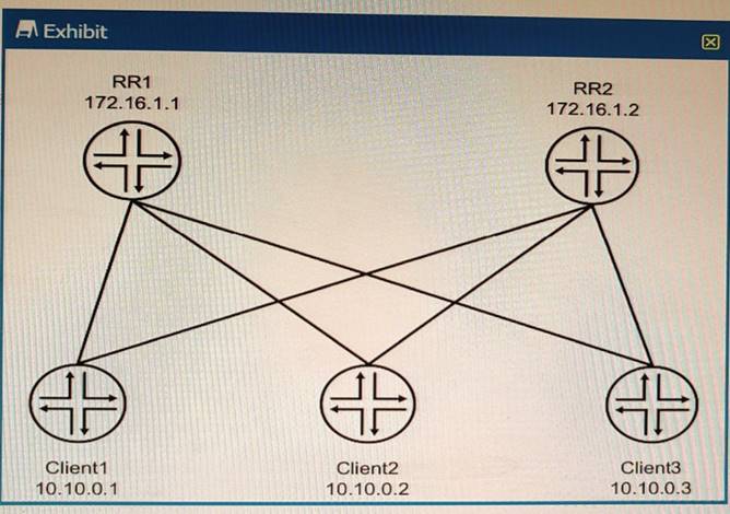
The environment is using BGP All devices are in the same AS with reachability redundancy Referring to the exhibit, which statement is correct?
- A. RR1 is peered to Client2 and RR2
- B. RR2 is in an OpenConfirm State until RR1 becomes unreachable.
- C. Client1 is peered to Client2 and Client3.
- D. Peering is dynamically discovered between all devices.
Answer: A
Explanation:
BGP route reflectors are BGP routers that are allowed to ignore the IBGP loop avoidance rule and advertise IBGP learned routes to other IBGP peers under specific conditions. BGP route reflectors can reduce the number of IBGP sessions and updates in a network by eliminating the need for a full mesh of IBGP peers. BGP route reflectors can have three types of peerings:
✑ EBGP neighbor: A BGP router that belongs to a different autonomous system (AS) than the route reflector.
✑ IBGP client neighbor: An IBGP router that receives reflected routes from the route reflector. A client does not need to peer with other clients or non-clients.
✑ IBGP non-client neighbor: An IBGP router that does not receive reflected routes from the route reflector. A non-client needs to peer with other non-clients and the route reflector.
In the exhibit, we can see that RR1 and RR2 are route reflectors in the same AS with reachability redundancy. They have two types of peerings: EBGP neighbors (R1 and R4) and IBGP client neighbors (Client1, Client2, and Client3). RR1 and RR2 are also peered with each other as IBGP non-client neighbors.
NEW QUESTION 5
You are configuring a BGP signaled Layer 2 VPN across your MPLS enabled core network. In this scenario, which statement is correct?
- A. You must assign a unique site number to each attached site's configuration.
- B. This type of VPN only supports Ethernet interfaces when connecting to CE devices.
- C. This type of VPN requires the support of the inet-vpn NLRI on all core BGP devices
- D. You must use the same route-distinguiaher value on both PE devices.
Answer: C
Explanation:
BGP signaled Layer 2 VPN is a type of VPN that uses BGP to distribute VPN labels and information for Layer 2 connectivity between sites over an MPLS network. BGP signaled Layer 2 VPN requires the support of the l2vpn NLRI on all core BGP devices1. The l2vpn NLRI is a new address family that carries Layer 2 VPN information such as the VPN identifier, the attachment circuit identifier, and the route distinguisher. The l2vpn NLRI is used for both auto-discovery and signaling of Layer 2 VPNs2. In this scenario, we are configuring a BGP signaled Layer 2 VPN across an MPLS enabled core network.
Therefore, we need to ensure that all core BGP devices support the l2vpn NLRI. References: 1: https://www.juniper.net/documentation/us/en/software/junos/vpn-l2/topics/concept/vpn-layer-2-overview.html 2: https://www.cisco.com/c/en/us/td/docs/ios-xml/ios/mp_l2_vpns/configuration/xe-16/mp-l2-vpns-xe-16-book/vpls-bgp-signaling-l2vpn- inter-as-option-a.html
NEW QUESTION 6
Exhibit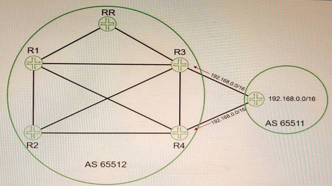
Referring to the exhibit, you are receiving the 192.168 0 0/16 route on both R3 and R4 from your EBGP neighbor You must ensure that R1 and R2 receive both BGP routes from the route reflector
In this scenario, which BGP feature should you configure to accomplish this behavior?
- A. add-path
- B. multihop
- C. multipath
- D. route-target
Answer: A
Explanation:
BGP add-path is a feature that allows the advertisement of multiple paths through the same peering session for the same prefix without the new paths implicitly replacing any previous paths. This behavior promotes path diversity and reduces multi-exit discriminator (MED) oscillations. BGP add-path is implemented by adding a path identifier to each path in the NLRI. The path identifier can be considered as something similar to a route distinguisher in VPNs, except that a path ID can apply to any address family. Path IDs are unique to a peering session and are generated for each network3. In this question, we have a route reflector (RR) that receives two routes for the same prefix (192.168.0.0/16) from an EBGP neighbor. By default, the RR will only advertise its best path to its clients (R1 and R2). However, we want R1 and R2 to receive both routes from the RR. To achieve this, we need to configure BGP add-path on the RR and enable it to send multiple paths for the same prefix to its clients.
Reference: 3: https://www.cisco.com/c/en/us/td/docs/ios-
xml/ios/iproute_bgp/configuration/xe-16/irg-xe-16-book/bgp-additional-paths.html
NEW QUESTION 7
Exhibit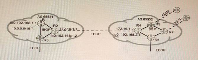
Referring to the exhibit, which three statements are correct about route 10 0 0.0/16 when using the default BGP advertisement rules'? (Choose three.)
- A. R1 will prepend AS 65531 when advertising 10 0.0 0/16 to R2.
- B. R1 will advertise 10.0.0.0/16 to R2 with 192 168 1 1 as the next hop.
- C. R2 will advertise 10.0.0.0/16 to R3 with 192.168.1 1 as the next hop
- D. R4 will advertise 10 0.0 0/16 to R6 with 172.16 1 1 as the next hop
- E. R2 will advertise 10.0.0.0/16 to R4 with 172.16.1.1 as the next hop
Answer: BDE
Explanation:
The problem in this scenario is that R1 and R8 are not receiving each other’s routes because of private AS numbers in the AS path. Private AS numbers are not globally unique and are not advertised to external BGP peers. To solve this problem, you need to do the following:
✑ Configure loops on routers in AS 65412 and advertise-peer-as on routers in AS 64498. This allows R5 and R6 to advertise their own AS number (65412) instead of their peer’s AS number (64498) when sending updates to R7 and R8. This prevents a loop detection issue that would cause R7 and R8 to reject the routes from R5 and R62.
✑ Configure remove-private on advertisements from AS 64497 toward AS 64498 and from AS 64500 toward AS 64499. This removes any private AS numbers from the AS path before sending updates to external BGP peers. This allows R2 and R3 to receive the routes from R1 and R4, respectively3.
NEW QUESTION 8
Which two statements are correct about the customer interface in an LDP-signaled pseudowire? (Choose two)
- A. When the encapsulation is vlan-ccc or extended-vlan-ccc, the configured VLAN tag is not included in the control plane LDP advertisement
- B. When the encapsulation is ethernet-ccc, only frames without a VLAN tag are accepted in the data plane
- C. When the encapsulation is vLan-ccc or extended-vlan-ccc, the configured VLAN tag is included in the control plane LDP advertisement
- D. When the encapsulation is ethemet-ccc, tagged and untagged frames are both accepted in the data plane.
Answer: CD
Explanation:
The customer interface in an LDP-signaled pseudowire is the interface on the PE router that connects to the CE device. An LDP-signaled pseudowire is a type of Layer 2 circuit that uses LDP to establish a point-to-point connection between two PE routers over an MPLS network. The customer interface can have different encapsulation types depending on the type of traffic that is carried over the pseudowire. The encapsulation types are ethernet-ccc, vlan-ccc, extended-vlan-ccc, atm-ccc, frame-relay- ccc, ppp-ccc, cisco-hdlc-ccc, and tcc-ccc. Depending on the encapsulation type, the customer interface can accept or reject tagged or untagged frames in the data plane, and include or exclude VLAN tags in the control plane LDP advertisement. The following table summarizes the behavior of different encapsulation types:
NEW QUESTION 9
Which statement is correct about IS-IS when it performs the Dijkstra algorithm?
- A. The local router moves its own local tuples into the candidate database
- B. When a new neighbor ID in the tree database matches a router ID in the LSDB, the neighbor ID is moved to the candidate database
- C. Tuples with the lowest cost are moved from the tree database to the LSDB.
- D. The algorithm will stop processing once the tree database is empty.
Answer: A
Explanation:
IS-IS is a link-state routing protocol that uses the Dijkstra algorithm to compute the shortest paths between nodes in a network. The Dijkstra algorithm maintains three data structures: a tree database, a candidate database, and a link-state database (LSDB). The tree database contains the nodes that have been visited and their shortest distances from the source node. The candidate database contains the nodes that have not been visited yet and their tentative distances from the source node. The LSDB contains the topology information of the network, such as the links and their costs.
The Dijkstra algorithm works as follows:
✑ The local router moves its own local tuples into the tree database. A tuple consists of a node ID, a distance, and a parent node ID. The local router’s tuple has a distance of zero and no parent node.
✑ The local router moves its neighbors’ tuples into the candidate database. The neighbors’ tuples have distances equal to the costs of the links to them and parent node IDs equal to the local router’s node ID.
✑ The local router selects the tuple with the lowest distance from the candidate database and moves it to the tree database. This tuple becomes the current node.
✑ The local router updates the distances of the current node’s neighbors in the candidate database by adding the current node’s distance to the link costs. If a shorter distance is found, the parent node ID is also updated.
✑ The algorithm repeats steps 3 and 4 until either the destination node is reached or the candidate database is empty.
NEW QUESTION 10
After a recent power outage, your manager asks you to investigate ways to automatically reduce the impact caused by suboptimal routing in your OSPF and OSPFv3 network after devices reboot.
Which three configuration statements accomplish this task? (Choose three.)
- A. set protocols ospf overload timeout 900
- B. set protocols ospf3 realm ipv4-unicast overload timeout 900
- C. set protocols ospf overload
- D. set protocols oapf3 overload timeout 900
- E. set protocols ospf3 overload
Answer: AE
Explanation:
To reduce the impact of suboptimal routing in OSPF and OSPFv3 after devices reboot, you can use the overload feature to prevent a router from being used as a transit router for a specified period of time. This allows the router to stabilize its routing table before forwarding traffic for other routers. To enable the overload feature, you need to do the following:
✑ For OSPF, configure the overload statement under [edit protocols ospf] hierarchy level. You can also specify a timeout value in seconds to indicate how long the router should remain in overload state after it boots up. For example, set protocols ospf overload timeout 900 means that the router will be in overload state for 15 minutes after it boots up.
✑ For OSPFv3, configure the overload statement under [edit protocols ospf3] hierarchy level. You can also specify a realm (ipv4-unicast or ipv6-unicast) and a timeout value in seconds to indicate how long the router should remain in overload state after it boots up for each realm. For example, set protocols ospf3 realm ipv4- unicast overload timeout 900 means that the router will be in overload state for 15 minutes after it boots up for IPv4 unicast routing.
NEW QUESTION 11
In which two ways does OSPF prevent routing loops in multi-area networks? (Choose two.)
- A. All areas are required to connect as a full mesh.
- B. The LFA algorithm prunes all looped paths within an area.
- C. All areas are required to connect to area 0.
- D. The SPF algorithm prunes looped paths within an area.
Answer: CD
Explanation:
OSPF is an interior gateway protocol that uses link-state routing to exchange routing information among routers within a single autonomous system. OSPF prevents routing loops in multi-area networks by using two methods: area hierarchy and SPF algorithm. Area hierarchy is the concept of dividing a large OSPF network into smaller areas that are connected to a backbone area (area 0). This reduces the amount of routing information that each router has to store and process, and also limits the scope of link-state updates within each area. All areas are required to connect to area 0 either directly or through virtual links2. SPF algorithm is the method that OSPF uses to calculate the shortest path to each destination in the network based on link-state information. The SPF algorithm runs on each router and builds a shortest-path tree that represents the topology of the network from the router’s perspective. The SPF algorithm prunes looped paths within an area by choosing only one best path for each destination3.
References: 2: https://www.juniper.net/documentation/us/en/software/junos/ospf/topics/concept/ospf-area- overview.html 3: https://www.juniper.net/documentation/us/en/software/junos/ospf/topics/concept/ospf-spf- algorithm-overview.html
NEW QUESTION 12
What is the correct order of packet flow through configurable components in the Junos OS CoS features?
- A. Multifield Classifier -> Behavior Aggregate Classifier -> Input Policer -> Forwarding Policy Options -> Fabric Scheduler -> Output Policer -> Rewrite Marker -> Scheduler/Shaper/RED
- B. Behavior Aggregate Classifier -> Multifield Classifier -> Input Policer -> Forwarding Policy Options -> Fabric Scheduler -> Output Policer -> Scheduler/Shaper/RED -> Rewrite Marker
- C. Behavior Aggregate Classifier -> Input Policer -> Multifield Classifier -> Forwarding Policy Options -> Fabric Scheduler -> Output Policer -> Scheduler/Shaper/RED -> Rewrite Marker
- D. Behavior Aggregate Classifier -> Multifield Classifier -> Input Policer -> Forwarding Policy Options -> Fabric Scheduler -> Scheduler/Shaper/RED -> Output Policer -> Rewrite Marker
Answer: C
Explanation:
The correct order of packet flow through configurable components in the Junos OS CoS features is as follows:
✑ Behavior Aggregate Classifier: This component uses a single field in a packet header to classify traffic into different forwarding classes and loss priorities based on predefined or user-defined values.
✑ Input Policer: This component applies rate-limiting and marking actions to incoming traffic based on the forwarding class and loss priority assigned by the classifier.
✑ Multifield Classifier: This component uses multiple fields in a packet header to classify traffic into different forwarding classes and loss priorities based on user- defined values and filters.
✑ Forwarding Policy Options: This component applies actions such as load balancing, filtering, or routing to traffic based on the forwarding class and loss priority assigned by the classifier.
✑ Fabric Scheduler: This component schedules traffic across the switch fabric based on the forwarding class and loss priority assigned by the classifier.
✑ Output Policer: This component applies rate-limiting and marking actions to outgoing traffic based on the forwarding class and loss priority assigned by the classifier.
✑ Scheduler/Shaper/RED: This component schedules, shapes, and drops traffic at the egress interface based on the forwarding class and loss priority assigned by the classifier.
✑ Rewrite Marker: This component rewrites the code-point bits of packets leaving an interface based on the forwarding class and loss priority assigned by the classifier.
NEW QUESTION 13
Exhibit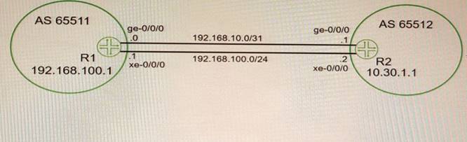
You want to use both links between R1 and R2 Because of the bandwidth difference between the two links, you must ensure that the links are used as much as possible.
Which action will accomplish this goal?
- A. Define a policy to tag routes with the appropriate bandwidth community.
- B. Disable multipath.
- C. Ensure that the metric-out parameter on the Gigabit Ethernet interface is higher than the 10 Gigibit Ethernet interface.
- D. Enable per-prefix load balancing.
Answer: D
Explanation:
VPLS is a Layer 2 VPN technology that allows multiple sites to connect over a shared IP/MPLS network as if they were on the same LAN. VPLS tunnels can be signaled using either Label Distribution Protocol (LDP) or Border Gateway Protocol (BGP). In this question, we have two links between R1 and R2 with different bandwidths (10 Gbps and 1 Gbps). We want to use both links as much as possible for VPLS traffic. To achieve this, we need to enable per-prefix load balancing on both routers. Per-prefix load balancing is a feature that allows a router to distribute traffic across multiple equal-cost or unequal- cost paths based on the destination prefix of each packet. This improves the utilization of multiple links and provides better load sharing than per-flow load balancing, which distributes traffic based on a hash of source and destination addresses4. Per-prefix load balancing can be enabled globally or per interface using the load-balance per-packet command.
Reference: 4: https://www.cisco.com/c/en/us/support/docs/multiprotocol-label-switching-mpls/mpls/137544-technote-mpls-00.html
NEW QUESTION 14
Exhibit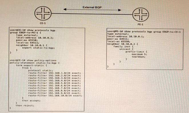
CE-1 must advertise ten subnets to PE-1 using BGP Once CE-1 starts advertising the subnets to PE-1, the BGP peering state changes to Active.
Referring to the CLI output shown in the exhibit, which statement is correct?
- A. CE-1 is advertising its entire routing table.
- B. CE-1 is configured with an incorrect peer AS
- C. The prefix limit has been reached on PE-1
- D. CE-1 is unreachable
Answer: B
Explanation:
The problem in this scenario is that CE-1 is configured with an incorrect peer AS number for its BGP session with PE-1. The CLI output shows that CE-1 is using AS 65531 as its local AS number and AS 65530 as its peer AS number. However, PE-1 is using AS 65530 as its local AS number and AS 65531 as its peer AS number. This causes a mismatch in the BGP OPEN messages and prevents the BGP session from being established. To solve this problem, CE-1 should configure its peer AS number as 65530 under [edit protocols bgp group external] hierarchy level.
NEW QUESTION 15
Which two statements are correct about IS-IS interfaces? (Choose two.)
- A. If a broadcast interface is in both L1 and L2, one combined hello message is sent for both levels.
- B. If a point-to-point interface is in both L1 and L2, separate hello messages are sent for each level.
- C. If a point-to-point interface is in both L1 and L2, one combined hello message is sent for both levels.
- D. If a broadcast interface is in both L1 and L2, separate hello messages are sent for each level
Answer: BD
Explanation:
IS-IS supports two levels of routing: Level 1 (intra-area) and Level 2 (interarea). An IS-IS router can be either Level 1 only, Level 2 only, or both Level 1 and Level 2. A router that is both Level 1 and Level 2 is called a Level 1-2 router. A Level 1-2 router sends separate hello messages for each level on both point-to-point and broadcast interfaces1. A point-to-point interface provides a connection between a single source and a single destination. A broadcast interface behaves as if the router is connected to a LAN.
NEW QUESTION 16
Which two statements are correct about a sham link? (Choose two.)
- A. It creates an OSPF multihop neighborship between two PE routers.
- B. It creates a BGP multihop neighborship between two PE routers.
- C. The PEs exchange Type 1 OSPF LSAs instead of Type 3 OSPF LSAs for the L3VPN routes
- D. The PEs exchange Type 3 OSPF LSAs instead of Type 1 OSPF LSAs for the L3VPN routes.
Answer: AC
Explanation:
A sham link is a logical link between two PE routers that belong to the same OSPF area but are connected through an L3VPN. A sham link makes the PE routers appear as if they are directly connected, and prevents OSPF from preferring an intra-area back door link over the VPN backbone. A sham link creates an OSPF multihop neighborship between the PE routers using TCP port 646. The PEs exchange Type 1 OSPF LSAs instead of Type 3 OSPF LSAs for the L3VPN routes, which allows OSPF to use the correct metric for route selection1.
NEW QUESTION 17
You are asked to protect your company's customers from amplification attacks. In this scenario, what is Juniper's recommended protection method?
- A. ASN prepending
- B. BGP FlowSpec
- C. destination-based Remote Triggered Black Hole
- D. unicast Reverse Path Forwarding
Answer: C
Explanation:
amplification attacks are a type of distributed denial-of-service (DDoS) attack that exploit the characteristics of certain protocols to amplify the traffic sent to a victim. For example, an attacker can send a small DNS query with a spoofed source IP address to a DNS server, which will reply with a much larger response to the victim. This way, the attacker can generate a large amount of traffic with minimal resources.
One of the methods to protect against amplification attacks is destination-based Remote Triggered Black Hole (RTBH) filtering. This technique allows a network operator to drop traffic destined to a specific IP address or prefix at the edge of the network, thus preventing it from reaching the victim and consuming bandwidth and resources. RTBH filtering can be implemented using BGP to propagate a special route with a next hop of 192.0.2.1 (a reserved address) to the edge routers. Any traffic matching this route will be discarded by the edge routers.
NEW QUESTION 18
An interface is configured with a behavior aggregate classifier and a multifield classifier How will the packet be processed when received on this interface?
- A. The packet will be discarded.
- B. The packet will be processed by the BA classifier first, then the MF classifier.
- C. The packet will be forwarded with no classification changes.
- D. The packet will be processed by the MF classifier first, then the BA classifier.
Answer: C
Explanation:
behavior aggregate (BA) classifiers and multifield (MF) classifiers are two types of classifiers that are used to assign packets to a forwarding class and a loss priority based on different criteria. The forwarding class determines the output queue for a packet. The loss priority is used by a scheduler to control packet discard during periods of congestion.
A BA classifier maps packets to a forwarding class and a loss priority based on a fixed- length field in the packet header, such as DSCP, IP precedence, MPLS EXP, or IEEE 802.1p CoS bits. A BA classifier is computationally efficient and suitable for core devices that handle high traffic volumes. A BA classifier is useful if the traffic comes from a trusted source and the CoS value in the packet header is trusted.
An MF classifier maps packets to a forwarding class and a loss priority based on multiple fields in the packet header, such as source address, destination address, protocol type, port number, or VLAN ID. An MF classifier is more flexible and granular than a BA classifier and can match packets based on complex filter rules. An MF classifier is suitable for edge devices that need to classify traffic from untrusted sources or rewrite packet headers.
You can configure both a BA classifier and an MF classifier on an interface. If you do this, the BA classification is performed first and then the MF classification. If the two classification results conflict, the MF classification result overrides the BA classification result.
Based on this information, we can infer the following statements:
✑ The packet will be discarded. This is not correct because the packet will not be discarded by the classifiers unless it matches a filter rule that specifies discard as an action. The classifiers only assign packets to a forwarding class and a loss priority based on their match criteria.
✑ The packet will be processed by the BA classifier first, then the MF classifier. This is correct because if both a BA classifier and an MF classifier are configured on an interface, the BA classification is performed first and then the MF classification. If they conflict, the MF classification result overrides the BA classification result.
✑ The packet will be forwarded with no classification changes. This is not correct because the packet will be classified by both the BA classifier and the MF classifier if they are configured on an interface. The final classification result will determine which output queue and which discard policy will be applied to the packet.
✑ The packet will be processed by the MF classifier first, then the BA classifier. This is not correct because if both a BA classifier and an MF classifier are configured on an interface, the BA classification is performed first and then the MF classification. If they conflict, the MF classification result overrides the BA classification result.
NEW QUESTION 19
When using OSPFv3 for an IPv4 environment, which statement is correct?
- A. OSPFv3 only supports IPv4.
- B. OSPFv3 supports both IPv6 and IPv4, but not in the same routing instance.
- C. OSPFv3 is not backward compatible with IPv4
- D. OSPFv3 supports IPv4 only on interfaces with family inet6 defined
Answer: C
Explanation:
OSPFv3 is an extension of OSPFv2 that supports IPv6 routing and addressing. OSPFv3 is not backward compatible with IPv4 because it uses a different packet format and a different link-state advertisement (LSA) structure than OSPFv2. OSPFv3 also uses IPv6 link-local addresses as router IDs and neighbor addresses, instead of IPv4 addresses. To use OSPFv3 for an IPv4 environment, you need to enable the IPv4 unicast address family under [edit protocols ospf3] hierarchy level and configure IPv4 addresses on the interfaces.
NEW QUESTION 20
......
Recommend!! Get the Full JN0-664 dumps in VCE and PDF From Dumps-hub.com, Welcome to Download: https://www.dumps-hub.com/JN0-664-dumps.html (New 65 Q&As Version)